

A situation many can relate to: an empty smartphone battery and no outlet around! That’s exactly why I recycled an old laptop battery into an USB power bank.
Follow the link for the full article with close ups of the electronics and insights into the building process.
This article will show you the basic powerbank circuit consisting of Lithium cell charging circuit, boost converter and toggle switch as well as my improved version with self activating boost converter and LED status indicator and homemade housing.

It all started with an old Lenovo laptop battery. I carefully pried it open to examine the cells. Three packs of two parallel 18650 Lithium 2200 mAh cells were connected in series.

According to some internet research about these cells, one should be able to use all three of these packs in parallel, as long as all the individual packs of two have intact cells.
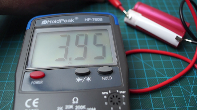
Simply measuring their voltage, carefully charging them under controlled conditions and checking if they hold their charge for quite some time determined all cells were still fine.

That means I will solder the three double packs in parallel for my USB powerbank. One can also just use one double pack and have a smaller, lighter power bank.

The next crucial part for a USB powerbank is the charging circuit board. For this I chose a cheap allrounder board: T4056 with power output control. This means the circuit does not only charge your Lithium cells in a controlled matter, but also provides contacts for an electric load. It cuts off power to the load if the cells’ voltage drops beneath ~3.7 Volts thus protecting the battery pack from deep discharge damages.


Now since the cells are connected in parallel we need to find a circuit that boosts up the voltage from the batteries’ range to 5 Volts for USB power. Luckily this problem has been solved hundreds of times before: USB boost converter. This USB converter circuit even has a power status LED.


To be able to turn the whole circuit on and off, the basic circuit will have a standard toggle switch in series with the USB boost converter circuit.
The T4056 is connected to the battery pack using the board’s +BAT and -BAT contacts.
The boost converter’s ground and the toggle switch’s positive remaining wire connect to the board’s -OUT and +OUT.
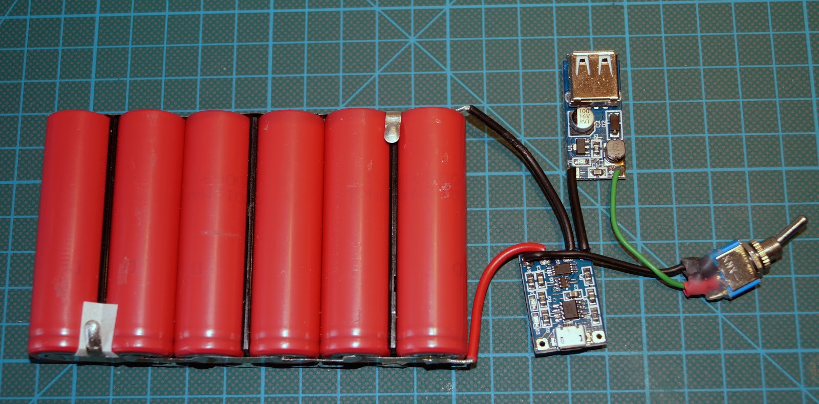
The basic circuit is finished now. The toggle switch is needed, since the boost converter allways draws power from the batteries, even if there’s no USB device plugged in.
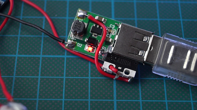
This and my being too lazy to use toggle switches leads to my quickfix makeshift improved version. I replaced the toggle switch with a lever switch and tried to install it in a way a plugged in USB plug would push it. These are the two solutions I came up with:
This and my being too lazy to use toggle switches leads to my quickfix makeshift improved version. I replaced the toggle switch with a lever switch and tried to install it in a way a plugged in USB plug would push it. These are the two solutions I came up with:
One has the lever switch mounted to the USB socket’s side. Inserting an USB plug pushes the switch’s pin.

A more complicated but less space consuming setup consists of a guided pushrod linked with another switch’s lever.


I chose this version despite its complicated workings because it fit better into my planned new enclosure.
The first enclosure was a slightly too tight messy plastic box I found somewhere between my tools. In light of recent events not the best idea to have a mean looking power bank when travelling in public transport… .


For the new enclosure I planned on cutting out wooden frames, stacking them and closing the whole thing with a top and bottom layer.


This would mean one could not see the USB boost converter’s and charing circuit’s LEDs anymore. Another layer of acrylic glass and connected smd LEDs solved the problem:


With a bit of additional solder, sanding and glueing the project was finally finished. The new powerbank is very sturdy and looks surprisingly good.


Here is a video about the project:
http://www.doityourselfgadgets.com