
Let’s start with a warning: Don’t try this if you have no idea what you are doing. Coilgun experiments often run on high voltages so there’s a pretty great chance you’ll get electrocuted. I am not responsible for any injuries. This is a scientific small scale experiment meant to enhance our understanding of the physics behind electromagnetic acceleration.

A so called coilgun or gaussrifle is basically an electromagnetic linear accelerator. Coilguns use, as the name says, a coil in order to create a magnetic field – it’s a different setup than in a railgun!
A coilgun almost allways consists of these three basic components:
A coil made out of insulated wire.
(The wire used may look like bare copper wire, but it is enamelled wire).

Last but not least, a switch which connects the energy source to the coil. This could be a normal power switch, but since most coilguns have high currents I recommend using a thyristor.

How it works:We have a coil wound over a non-conductive tube which is a coilgun’s barrel then. It has to be non conductive (plastic or something comparable) because otherwise the coil’s magnetic field would simply cancel out itself inside the tube. The projectile has to be made of a ferro magnetic material, that means stuff that reacts to magnetic fields.If a short current pulse is passed through the coil via our charged capacitor and the switch, the projectile will be pulled into the coil. If the pulse ends before the projectile gets to the coil’s middle, it’ll leave with a gain in velocity. The main difficulties with coilguns are winding an appropriate coil, finding the appropriate voltage and capacity and of course timing and positioning of the ferromagnetic material in front of the coil. Here is a short animation of the magnetic field when a projectile enters the coil:

The more windings a coil has, the stronger is its magnetic field. But if you use too long and thin wire with your experimental coil setup, either the wire will eventually burn through or the coil’s electric resistance will go up and lower the current and thus weaken the magnetic field.
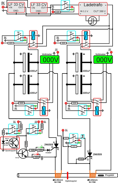
My test circuit looks like this:

I charged the capacitor with a little transformer circuit taken from a disposable camera’s flash.
If you don’t know how to charge a capacitor click here.
There’s a test video, too:
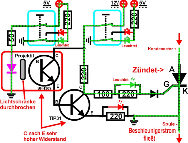
Further increasing of the velocity is possible by adding more stages which means not more than adding more coils. These coils need to be triggered automatically since the projectile is already in motion and you’re not able to push the button at the right moment. Many people use light barriers mounted in front of the second stage. Here’s a schematic of my second stage light barrier trigger (Ignore the safety switchtes and safety lights):
You can see the second stage, a light barrier in front of it and a little screw which gets pushed (normally it would fly through by itself due to the first stage) into the beam. I built this two staged test rig with multiple measurment devices in order to learn more about positioning of the projectile in front of the coil, the coil itself, capacity and voltage and timed triggering.
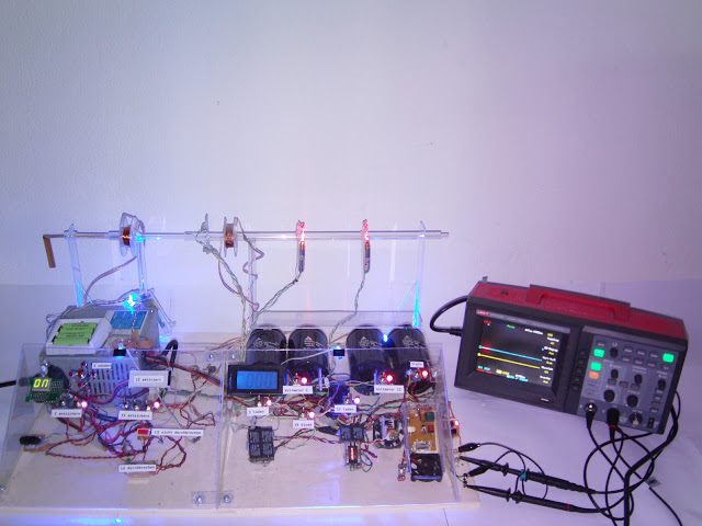
There are a lot of safety switches and control Leds just because of safety matters. Voltage range is from 0-400V and one stage has a capacity of 4400uF. I used several projectiles of different masses.
With a little positioning device I was able to test out many starting positions.
Due to a second measurement coil I was able to record the indirect magnetic pulse of the first stage firing. The other two peaks are for velocity measurement.

What are coilguns capable of?
Coilguns are scalable to very large applications, possibly as large as a mass driver to put payloads into orbit. It has no moving parts thus there’s the magic of invisible forces at work. It requires no special construction techniques or unusual tools. The coilgun technique can also be used to build so called levitrons which are “no gravity hovering devices”.Click here to see my coilgun models!